
In a previous blog post, I described connecting the Meraki MX to the internal network. In this blog post, I go through different ways to connect to the internet. The internal connection is not detailed here; this is independent of the external connection to the ISP.
Option 1: One MX, single ISP

This one is straightforward and only mentioned for completeness. Nothing special here.
Option 2: One MX, two ISPs
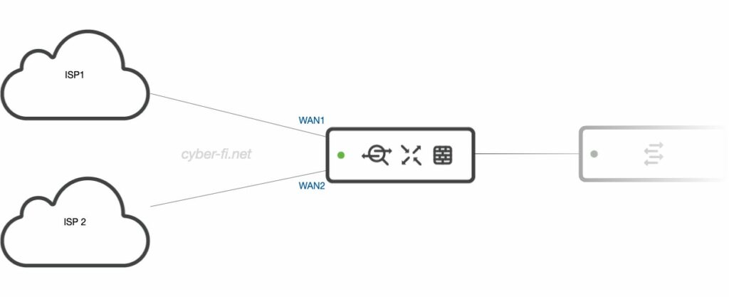
This setup is unlikely to be implemented. If we use two ISPs, we typically want to remove single points of failure. And having only one MX is one of these single points of failure. Implementing a warm spare MX only needs an additional device of the same type but no additional license. Implementing HA is relatively “cheap” compared to a Cisco FTD, where the secondary device also needs a subscription.
Besides that, this setup is again straightforward. On the low-end devices (e.g. MX67) one LAN port needs to be converted to a WAN port to implement a dual ISP setup.
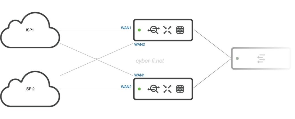
Option 3: Two MX, two ISPs (1)
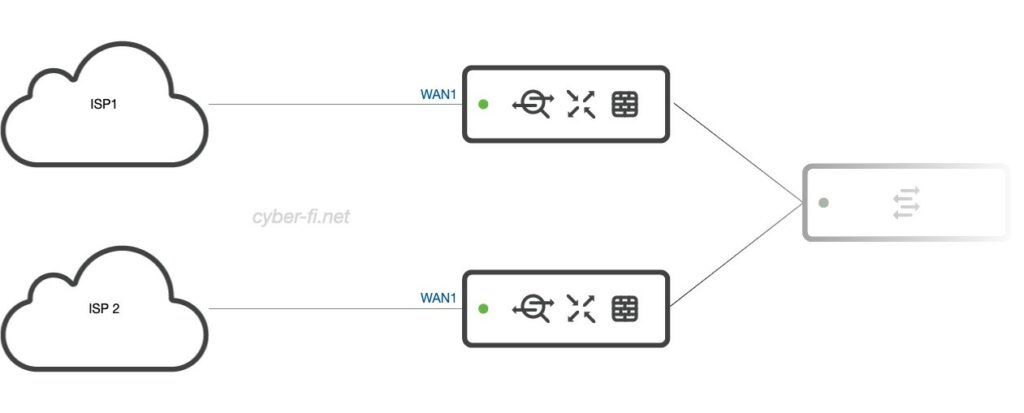
This is a setup that I typically try to avoid. MX1 is only connected to ISP1, and MX2 is only connected to ISP2. This could be used when the ISP only provides a single IP (PPPoE) or a /30 subnet. With only one IP available, we can’t connect both MX to that ISP as both MX need an IP for the dashboard communication. With a warm spare, we always want to get at least a /29 from the ISP, which gives us enough IPs for both MX and a virtual IP.
The major drawback of this setup is that every failover disrupts all connections to the internet. The usage of virtual IPs is not possible.
Option 4: Two MX, two ISPs (2)
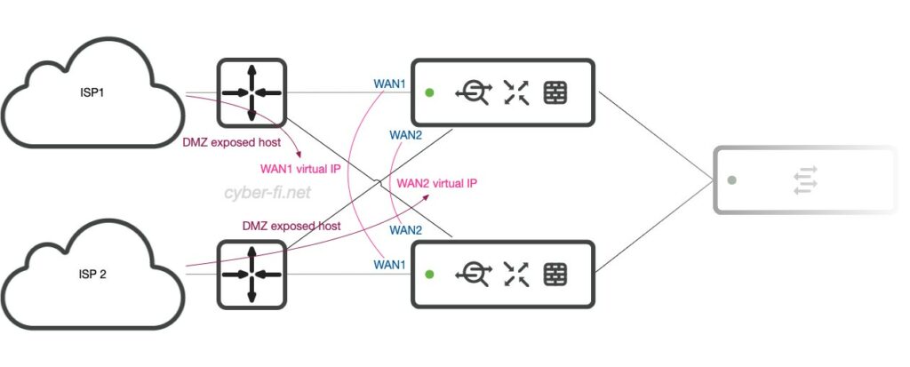
This is also not my favorite. But if we only have a /30 network or a single PPPoE IP from the provider, we can place a router in front of the MX. Here, we can choose a device with two switch ports to connect both MXs. With that, we can also use virtual IPs on the MX.
On the router we configure our Internet connection and transfer subnets between ISP1 router and WAN1 and also between ISP2 router and WAN2. The routers implement the NAT/PAT functionality and are configured to forward all traffic to the virtual IP.
Optionally, the MX can be configured with NAT exception. In this case we also need static routes on the router for the internal subnets pointing to the virtual IP. And we should be aware of the restrictions with this feature that are described in the referenced document.
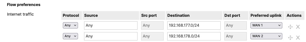
To manage the routers with the transfer-network IP, at least the non-primary connection needs a flow preference configured:
Option 5: Two MX, two ISPs (3)
This setup is, again, unlikely to be implemented. We have at least /29 subnets from the ISPs to connect both MX to the ISPs. Additionally, the ISP devices provide us with two ports to connect our firewalls. This is good as we don’t need any switch on the WAN-side, and we can use virtual IPs. But to my knowledge, having two ports available on business connections is relatively uncommon.
Option 6: Two MX, two ISPs (4)
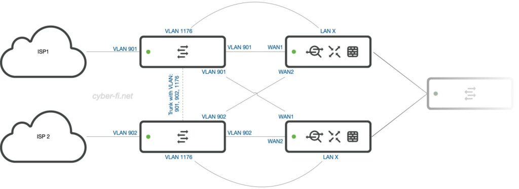
This is my typical setup. Two Meraki MX connect to two ISPs with only one port each and at least a /29 subnet. Now, we need additional WAN switches between the MX and the ISPs. My favorite device is the 8-Port Catalyst 1000, but I also use CBS350 for cost reasons. If you use a Meraki MS, put these switches into a separate dashboard network so the client sampling doesn’t get messed up.
What is in this setup:
- Each ISP gets a VLAN on the switches. In this example:
- VLAN 901 for ISP1
- VLAN 902 for ISP2
- The ISP devices and the MX WAN ports are connected to access ports in the corresponding VLAN.
- To manage these switches, an additional VLAN is configured on the MX and connected to an access port on the switches. This is VLAN 1176 in my example. Both switches get an IP in this VLAN.
- The MX has all the firewall rules to allow protocols like RADIUS/TACACS, NTP, SYSLOG.
- Both switches are connected with a trunk that carries these three VLANs.
- My typical Port setup is:
- 1-4: VLAN 901, ISP1
- 5-8: VLAN 902, ISP2
- 9: X-Connect between switches
- 10: Connection to MX in management VLAN 1176
The redundancy with this setup is quite high:
- Both MX have full Internet connectivity.
- We can use virtual IPs on the MX.
- In case of a switch failure, there are enough ports to patch both ISP devices and both MX on the remaining switch until the failed device is restored.
Another benefit is that we can connect an additional VPN firewall to the switch for the extranet VPNs to circumvent the many restrictions of the Meraki MX for this use case.
Option 7: Two MX, two ISPs, LTE/5G (1)
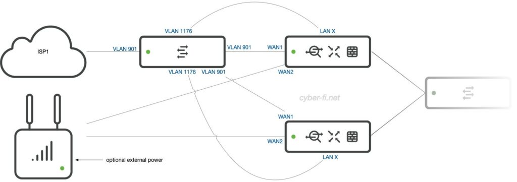
Let’s add a Meraki MG as one ISP connection. With the Meraki MX 85/95/105, this device can be powered with PoE from the MX WAN port. But there is a drawback: The MG only gets power from one port. If MX1 is used to power the MG and this MX fails, then the MG will reboot to receive power from MX2. An external power supply could also be used.
To manage the external switch, we need to connect it to both MX.
Option 8: Two MX, two ISP, LTE/5G (2)
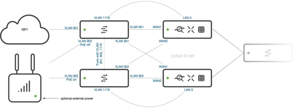
To overcome the drawback of the previous option and to be able to connect an additional VPN firewall, the second switch can be added back to the setup.
This is nearly the same as option 6. The connection from the upper switch to the MG doesn’t add much benefit, but if the MG is connected to both switches, PoE should be disabled on the upper switch. If that switch goes down, we lose ISP1. But if this switch also powers the MG, the MG will reboot to receive power from switch two. This will cause a complete downtime until the MG is operational again. Without PoE on switch one, a failed switch one will not impact ISP2. But a failed switch two will disrupt power to the MG, and this ISP will not be available regardless of the connection to switch one. As before, an external power supply could also be used here.
Option 9 to 374:
What about all the other ways, like one ISP but two MX? At least this is just a subset of option 4+ and doesn’t need any extra discussion.
The main points for the MX are:
- Both MX need a public IP. This is different from the ASA/FTD.
- Both HA devices can have different internet connections as shown in option 3.
- For any HA, we should have a /29 from each ISP to have enough addresses for both firewalls and a virtual IP.
- As of now (February 2024), IPv6 is still not supported with HA.
Conclusion
Whichever option you use, choose wisely!
Hi Karsten,
Wonderful post!
In Option 6, is it necessary to keep both ISP links in different VLANs or it can work by keeping both links in Same VLAN?
What are the advantages and disadvantages of having same VLAN or different VLANs for ISP links?
Having two VLANs is a much cleaner approach. It would work without, but for example, all broadcasts from/to ISP1 will show up on the ISP2 router and also the ISP2 MX interface. I don’t see a single benefit in not using VLANs here.
Hi Karsten,
Excellent post. We happen to have the same design as option 6, however, the downlinks from MX to a common switch, going with same vlan 500 the HA lan failover is not happening, actually, is getting both device to set current master. How can I go about this?
Great post.
I have a scenario that ISP1 is /29 and ISP2 is /31. Two MX and two Meraki WAN switches.
What is the best topology for this situation?
First, I would try to get a /29 from ISP2. If that is not possible, I would perhaps connect ISP1 to both MXes and ISP2 only to MX1. With that, you’ll only have ISP1 if MX1 fails, but you could prepare the ISP2-config on MX2 and just move the cable.
Karsten,
What is the recommendation for the WAN breakout switches, Stacking or Trunk between switches?
In general, I don’t use a stack here, but have a trunk link between them.
A stack would only be needed if the firewall needs to be connected with a channel to the WAN switches. But the MX doesn’t support this at all, and the Cisco Secure Firewall (formerly FTD) has redundant interfaces as an alternative.
what about having singe ISP with Two MX 105 Appliances ?
For that scenario, you can use Options 4 to 6 and just ignore everything about ISP2.
Have you ever used core switches with VRF/VLAN segmentation? ISPs are going to MS core switches one to each core then to MX cross and from MX to MS core switch back for other traffic also cross, this looks to be typical scenario for regular Cisco devices, why i do not see it here?
Yes, I also used that. But I try to avoid it as much as possible.
Every separation like VRF/VLAN is software. If for whatever reason the config is lost, or not yet applied while booting, we end up with a firewall that is temporarily bypassed by this switch.
It’s IMO just not worth it to save the money for two switches.
Hi Karsten, can I please ask what is the drawback of a topology similar to option 6 but instead of using 2 switches between the isp and mx devices, instead using 2 hubs and no cross connect? I understand I would not have management capability of the hubs however I am struggling to see the benefit of using switches here. What am I missing?
We have used the topology like the one I described for a retail store pop up, and it worked flawlessly. I would however like to find ways to improve the design. Thanks!
I also used unmanaged switches here (I don’t think we can buy hubs any more). But having no management is reason enough for me. And sometimes I also want to set a VLAN-tag pointing to the ISP.