Connecting the Meraki MX to an internal switched network? Sounds easy and if the network is build without any redundancy, it is very easy indeed:
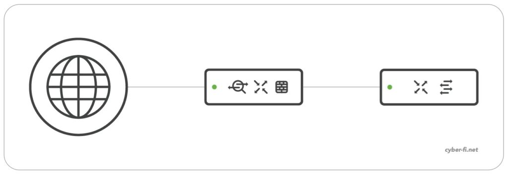
It can get a little bit problematic if redundancy is added. If you come from the Cisco ASA, you have tools like
- routed interfaces
- Port-Channel
But on the MX we have
- no port-channels
- switched interfaces
- no spanning-tree
In addition to that, we have Meraki switches that “only” support RSTP and no per-VLAN RSTP.
In the redundant setup, we have basically two options to connect the redundant MX firewalls to the redundant MS switches:
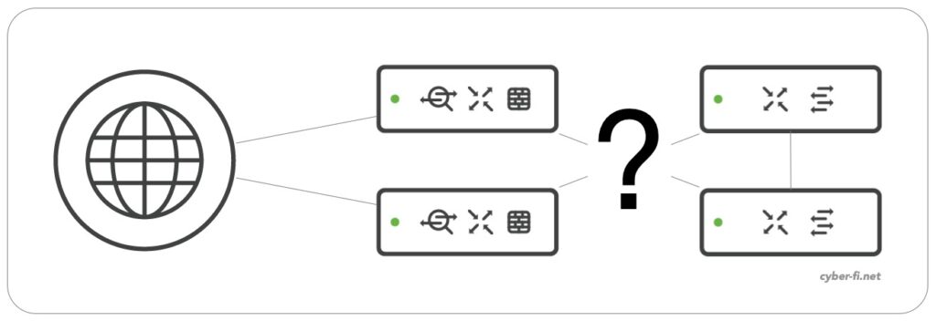
Option 1:
Based on Meraki documentation and best practice, both MX are connected to both switches and for this discussion, it is not relevant if the switches are standalone or stacked switches:
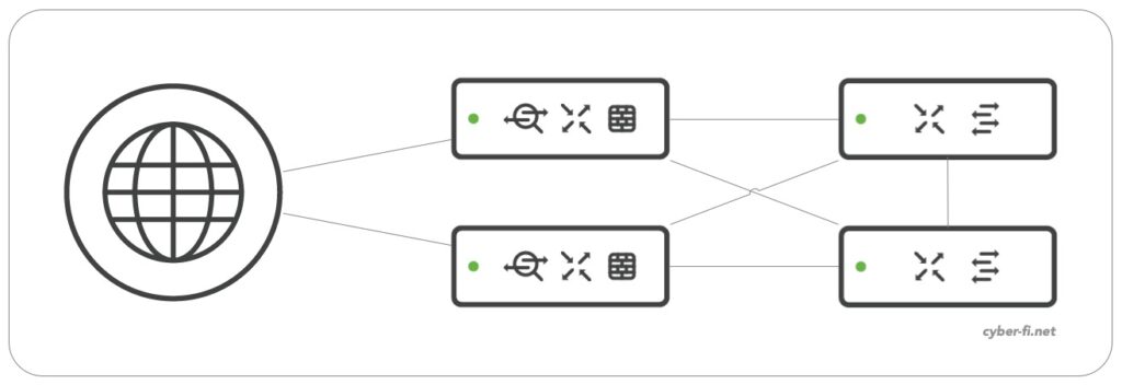
But from a Spanning-Tree view, the topology looks like this:
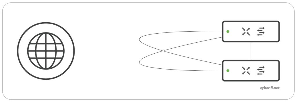
With the MX not participating in Spanning-Tree, we need to make sure that the switches can block one interface of each of these connections. For this we need to make sure that STP BPDUs can flow freely through the MX. When coming from an ASA background, you are probably used to have sub interfaces on the ASA, but not to configure the main-interface with a nameif, security-level and IP-address. Lets assume we configure something similar on the MX:
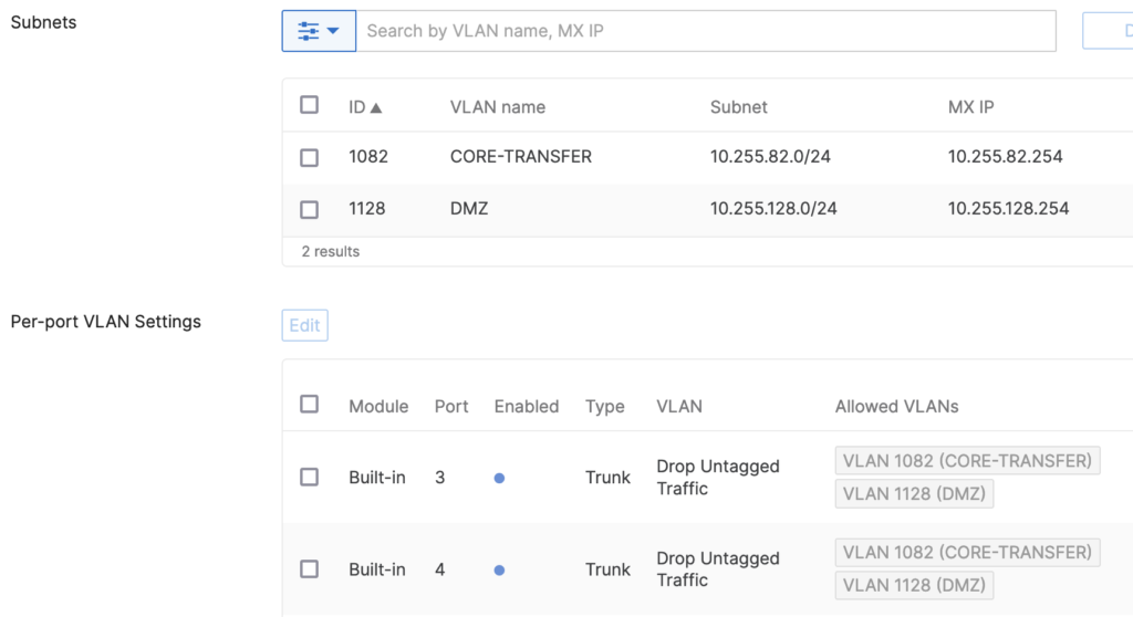
Although we only want to use the two tagged networks CORE-TRANSFER and DMZ, by dropping untagged traffic on the MX, we also drop BPDUs and Spanning-Tree can not block the two ports on the switches and the network is likely to be severely impacted.
If configured correctly, the ports that connect the two MX look like this:
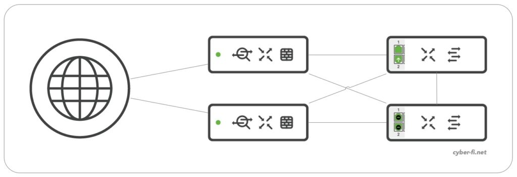
The upper switch has two STP designated ports, both are forwarding and the one with the white arrow indicates the connection to the active/primary MX. The second switch has two ports in the STP blocking state.
The switch ports connecting the MX have RSTP enabled, but no STP guard active:

What is the corresponding MX configuration? There are multiple ways to implement it, each with its own pros and cons. The easy way is the following (ignoring the best practice not to use VLAN1):
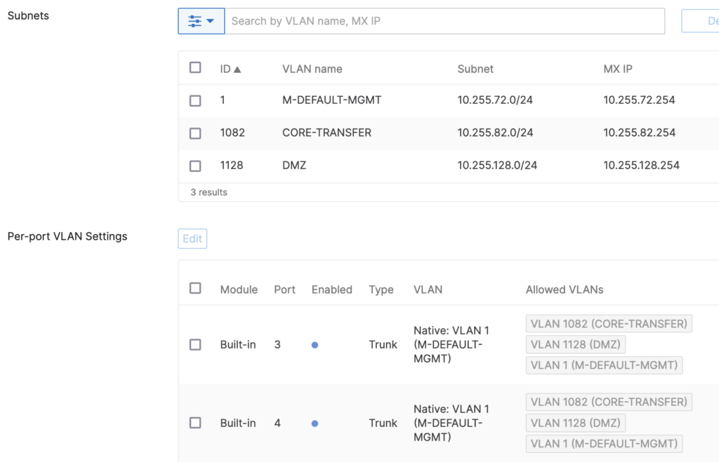
VLAN 1 is used as the native VLAN on the MX and is used for the management-ports of the connected Meraki MS switches. The default port- and management-vlan-configuration on the MS switches matches the MX config and no adjustment is needed. But special caution is needed to make sure no user-port is configured for VLAN 1 in this setup. Probably extra Firewall rules for VLAN 1 should allow Meraki Dashboard communication but nothing else in case a user is placed in VLAN 1 by mistake.
Alternatively we can use a different VLAN as the native VLAN:
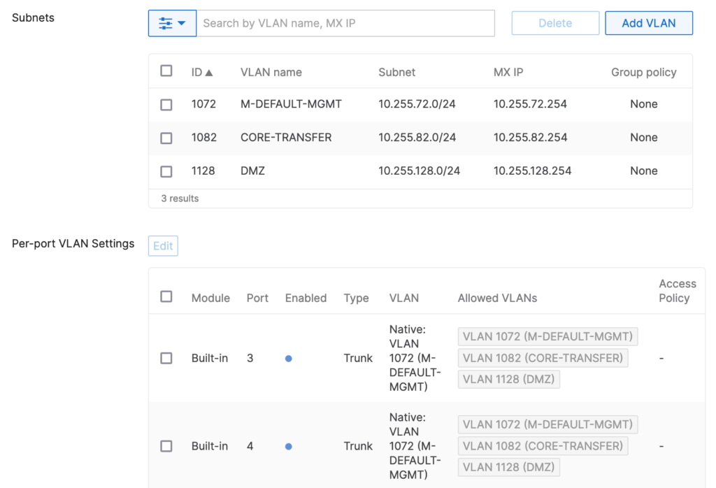
Now we need to make sure that the switches use this VLAN as the management-VLAN and also have this VLAN native on the uplinks. For this setup, the management VLAN was not configured individually on the “LAN IP”, it was set on the “Switch settings” page for all switches.
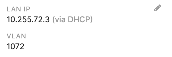

The main benefit is that users are not likely to be assigned to this VLAN by mistake.
Option 2:
In option 1 we rely on Spanning-Tree to block ports. Probably every network-admin in the world already faced problems with Spanning-Tree and/or caused unplanned downtimes by misconfiguring Spanning-Tree. For this reason a different approach could be used that has less redundancy, but can be more stable:
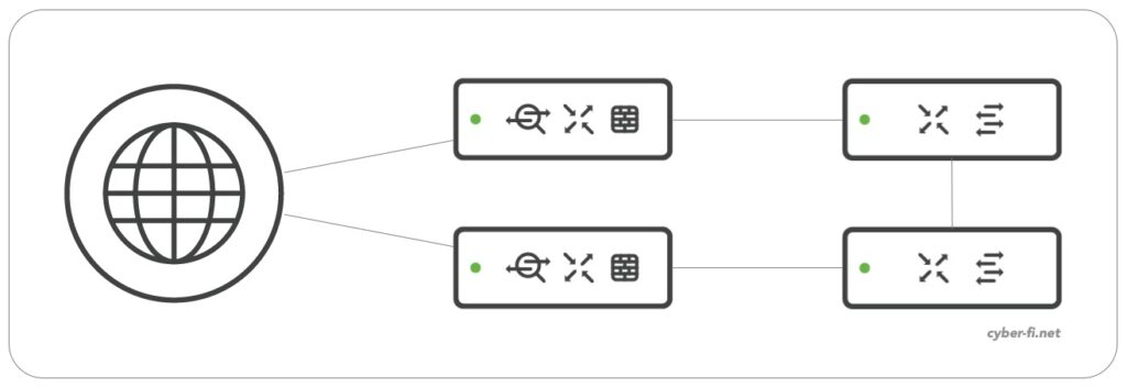
Each MX has only one connection to the switched network. Spanning-Tree is not needed any more to block ports, both switch ports that connect the MX firewalls are in the forwarding state. In this scenario we don’t need a native VLAN on the MX and we can drop untagged traffic without causing any problem.
Although this setup can be more stable, there is at least one major drawback (in addition to the reduced redundancy):
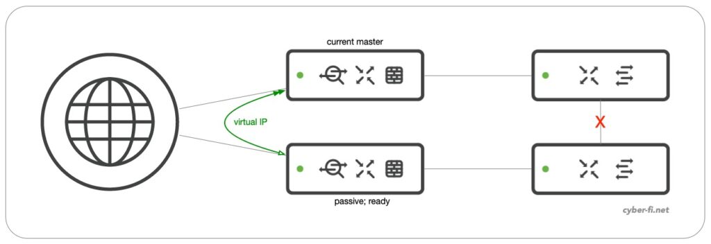
When the link between the two switches fail, we run into a split-brain situation (Anyone else already had a non-working stack-connection after a reboot?). VRRP between both MX can’t reach each other and both Firewalls become active:

For sure, this is a bad situation and you want to get out of it as fast as possible. But with option 2 it can even get worse. Both firewalls want to use the virtual IP but only one can do that. The part of the network that had the previous “Current master” likely has uninterrrupted internet connectivity. But the part of the network with the previous “passive, ready” will have limited connectivity.
When facing the problem some time ago in a “real” network, one switch completely lost connectivity to the dashboard which can make troubleshooting problematic if you are not onsite. While doing some more tests recently, the dashboard connectivity was delayed, but I was able to manage both switches and a PCAP showed that the spare MX fell back to its interface IP.
Recommendations?
I have no recommendation to generally use Option 1 or Option 2. Most of the time I prefer the oficially suggested way which is Option 1. Just be aware of how the network behaves and choose wisely!

Great article. Ran into this exact issue on a site deployment and this Article explained everything i was looking for. 10/10
Thank you for a good article. But i do have one question / concern. In Option 1 you have an alternative configuration “Alternatively we can use a different VLAN as the native VLAN”
When we assign a VLAN to the Management IP, i would assume the MS switches will actually tag the Management traffic with that VLAN ID.
If that is the case then it should not be necessary to have the same VLAN ID as the Native VLAN ID on the Trunk ports? Would it not make more sense to keep VLAN 1 as the Native VLAN on the Trunk Ports? Then STP traffic would end up in VLAN 1 and we would avoid having Clients connected to Management VLAN if they (accidentally) plug into a Trunk port?
If a Mgmt-VLAN is set, this traffic will be tagged by default. But if the uplink port defines this VLAN as native, traffic will be sent without a tag.
For the question of which strategy is better, well, I would say it depends. A good practice is not to have any untagged traffic on inter-switch links or links between routers/firewalls and switches. But this is hard to achieve in all situations. Keeping VLAN1 as native makes many things definitely easier.
Thanks for the article, in option 1, is it correct to say you don’t actually need the link between the 2 switches?
Technically, it could work without this link. But you would have highly suboptimal forwarding from switch one to switch two. So, we’ll likely have this link in our setup.
Thanks, really interesting and useful. What would you recommend if you had a switch in front of the Firewalls connecting to the WAN (ISP), would this be the same ?
ISP (x2) WAN Switch (x2) MX (x2) MS (x2)
I’ll do a separate blog post on that soon.
Hi Karsten,
thank you for the detailed overview. need your suggestion on setting up a high availability meraki network. I have two mxs , 2 ms410s and 6ms120. I want to go with option 1 here, by using 410 as CD switches and remaining ms120s as access switches. what do you think would be best network setup to maintain HA through out the access switches. do you think stacking ms410 would be best setup instead of using them as separate standalone CD ? please suggest
I typically would stack the MS410 and connect all access switches or access stacks with an ether channel to both 410. That will give you quite a good redundancy. For more advice and suggestions, you could always ask in the Meraki Community: https://community.meraki.com
I’m just thinking one thing. For option 2, what about if we connect a cable between two MXs with the same VLAN(s) for option 2? Seems the issue mentioned in option 2 can be resolved. Any one has opinion on this point?
That was a proposed solution many years ago, but now it is not recommended any more by Meraki to have this extra cable.
Thanks for your reply. Yeah…It’s not recommended by Meraki. Seems Meraki thinks this will cause spanning-tree loop. To be honest, I didn’t quite get this point. But I’m just thinking, if we can manage the spanning-tree loop, isn’t it a good way to resolve the issues in option 2? Right?
Hi Karsten,
First of all, thank you for this great article.
I would like to ask something, as we have a scenario similar to Option-2 ( where MS225 switches are stacked together ) and once we connected the second switch to the second MX250 we had a total blackout where we lost our connection. I want to emphasize that we had the opsion of native VLAN as “Dropp untagged traffic” but we also have another parallel switch stack ( of another vendos/Brocade switches) connected to MX devices. We are trying to remove this stack and change it with Meraki MS225 but as mentioned, we already had issues once connected the second cable to the passive MX device.
Would you please some insights here if the issue might be cause of no native VLAN specified or that parallel stack ( having the exact same VLANs allowed as the new Meraki stack ).
Thanks in advance !
It’s unclear to me how your exact setup was and how this has been caused. It is best to join the Meraki Community and describe your problem there with a detailed diagram: https://community.meraki.com
i Am having single connection to MX from the downstream Core switch stack,so which methods can you suggest for this kinds 0f setup. can i still use the the option-1 ?
With only one link, you are automatically on Option 2. Option 1 is based on the redundant setup.